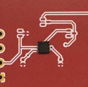
 Well, I blew it…again. This time with the IC footprint for the latest boards I received from JLCPCB, the 1-wire counter board for the rain gauge. I should have double checked the footprints before I sent it off for fabrication. Nuts. I guess I was careless picking a 6-pad footprint for the DS2423 counter chip. I used the SOT-23-6 Digikey footprint instead of a TSOC-6 one. I guess because I ordered these from Digikey long ago? I dunno. Good thing it’s only $2 for 5 boards, but it’s another setback. So on the left is a DS2423 positioned on the new footprint. I exported a color PDF of the board so I could test the fit. This works pretty well, to export a PDF, which is pretty much actual size.
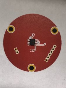 This next comparison shows a much better size footprint (SOIC-8) than I originally chose to use, fortunately, as a double check before I (again) send off the gerber and drill files <sigh>. And it appears there’s SO many SOIC-style footprints to choose from, which I think makes it kind of confusing. Especially for me, a Kicad EDA newbie, apparently.
This next pic shows the centering of the angle sensor using the mounting plate that held the original “precision” potentiometer . I won’t be using this plate – this is only a check. It looks good, but I may need to tweak the position some since there is a sweet spot with this chip. And I might have to maybe edit the TSOC-6 footprint for the rain gauge counter board (above) since I’m hand soldering these things. But so far this looks promising.