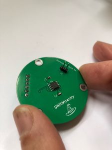
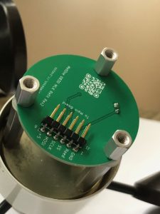
 Well, after screwing up the footprints for the IC’s on both PCB’s (this board AND the DS2423 rain gauge board), I soldered up the components on the anemometer refit board and it looks pretty good for a Kicad and SMT newbie. Only thing is, I got sort of a not-very-smooth solder joint on capacitor C2 on the GND side, but it WAS on a copper ground plane. Seems to be OK and not a cold solder joint. (My first SMT project.) Now onto the rain gauge project and solder up the DS2423 1-wire counter board – REV 2 🙂
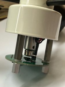
And the PCB fits nicely onto the mounting holes where the original potentiometer previously was. With many thanks to those far more experienced Kicad users on the Kicad forum who helped me figure out how to place the mounting holes EXACTLY 120 degrees apart. 
