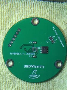
Back to the Kicad drawing board apparently. I inadvertently used the wrong IC outline for the MLX90316 sensor, which is an SOIC-8 package and I somehow thought SOT23-8 was the same. The Kicad footprint I used (SOT-23-8) is obviously smaller than the actual chip footprint at U1, as you can see.  Nuts. I should have double checked it. I found this out after soldering the 0603 SMT caps to the board. At least I didn’t solder the header pins to the board too! Soldering the caps worked out pretty well, but I found out that the diameter size of the solder I was using was about the size of the pads! And, as sort of expected, soldering to the ground plane side of the caps was more difficult that a expected because of heat sinking. So now version 2 of the board…fortunately they are cheap, and I wanted to make some changes anyway. On a comical side note: I was soldering one of the capacitors and in a blink of an eye (twang!) it just sprung out from my SMT tweezers! I probably landed on the carpet somewhere, so it’s GONE! Good thing I got 50 of them! OK, version 2 of the MLX refit in the works… guess these 5 boards will be used for SMT soldering practice. I did export a PDF of the board to see if the holes line up with the original plate the pot was mounted to; before I send THIS new version to JLCPCB I’ll check the chips pads on a new PDF… And I need like 0.5mm or smaller solder too..