As I mentioned in the page for my Weather Station project, the special “precision” potentiometer somehow was reading OPEN…no resistance measured at all when the pot shaft is turned. It was never out in the weather, so I can’t figure that one out! So, I found this article in Instructables about using a Melexis MLX90316 Hall effect angle sensor in a windvane. I have the sensor working on a breadboard with a ESP8266, sending data via MQTT to a Raspberry Pi MQTT broker, but now I need to see if the MLX90316 will work connected via a 6 to 8-foot cable to the ESP8266.
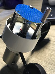
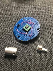
I cut a circular piece of phenolic breadboard to the same size as the mounting plate that the pot was mounted on; the sensor chip will be mounted on this board along with the necessary other components, and the magnet will be attached such that it will rotate above the sensor chip. A PCB using KiCAD is in the works…something else to learn… more on that later.
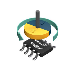 As shown in the image from the MLX90316 specifications PDF, when a diametrically magnetized magnet is positioned above the sensor, the output shows the angle. The issue now is to make a “temporary” coupling to attach the magnet to the shaft of the windvane. These special rare earth supermagnets when held above the MLX90316 angle sensor chip, cause it to output a signal corresponding to the angle. I’m using an N38 Neodymium ring-style magnet (RD0906) that I got from this site: https://www.gaussboys.com/. I
 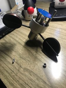 bought 3 of the cylindrical ones and 2 of this ring style. A couple word of warnings: if you buy the ring-style magnets, they are a bit fragile. I know…I just broke one when I held one of the cylindrical ones close and the ring one broke in half with the force of the attraction. Like, BAM! It split in half. These suckers are strong! That’s why in the image with the anemometer, they are like 6″ apart; any closer and they’d be TOGETHER! (And note: if you use this sensor, be aware that the magnet MUST be diametrically magnetized.)
Test Circuit for the MLX90316
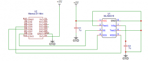
The circuit and software that decodes the signals from the angle sensor chip originally was found on the website for Academy of Media Arts Cologne, but apparently that site changed and the page for the sensor can’t be found. Fortunately, the code is available on GitHub in a few places, and I include the link here, but no there’s no accompanying schematic. I’m including it below.
 .
.
Using the circuit above connected up on a breadboard, and VSCode with the PlatformIO extension, I created an ESP8266 test program for the MLX90316 and the results are below. At first, after the “No SPI signal” line and manually holding and turning a ring-shaped DO (diametrically opposed) magnet above the sensor, the angle is reported in the output. I’ve found that, with this magnet, it needs to be positioned less than about 1/2″ above the sensor to register an angle, which is totally fine, since it should be about 1/4″ in the final version.
MLX90316 Rotary Position Sensor Test
No SPI signal (Initial error on start up. Pretty much normal)
angle = 163
angle = 164
angle = 130
angle = 132
angle = 87
angle = 84
angle = 143
angle = 205
angle = 236
angle = 263
Magnetic field too weak (Magnet pulled away)
Magnetic field too weak
…
It works great on the breadboard with the sensor chip in close proximity to the D1 Mini, but now for the REAL test: testing using an 8–10-foot cable.
Testing SPI Signals to Remote MLX90316
The left image below shows my proof-of-concept prototype. The circuit board only has the MLX90316 sensor chip soldered to an SOT-23 adapter (that was used for breadboard testing above), a couple of 0.1uF capacitors, and header connectors. I used one of the Neodymium magnets, the one that split in half, (but it fits the bill for testing) and fashioned an adapter from a plastic TV alignment tool, attaching the magnet carefully with caulk. That adapter then fits into the 1/8″ shaft coupler that originally was used to attach the potentiometer. So now, I can finish soldering the capacitors to the board, connect connector pins to an 8-10′ cable, and connect up the board to the main weather station unit and see if it works!
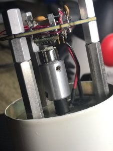
The purpose for this temporary test jig is to make sure the SPI signals do, indeed, work over like 8-10 feet of distance to the D1 Mini. I fashioned a connecting cable from a 10′ Cat-6 ethernet cable and during testing I was getting No SPI Signal repeatedly from the test program. Hmmm, apparently some of the header connectors weren’t making a good connection, which makes some sense because soldering these tiny pins is a bit of a challenge. (I can hardly wait to start soldering SMT devices. 😮 ).