As I mentioned in the About Me page, I’ve been into electronics for 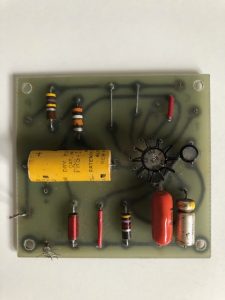 a LONG time…since I was like 13 and let the smoke out of a lot of transistors. Wish I had kept some those early transistors (more “junk” my wife would probably say 🙂 ), but then just for memories’ sake I suppose. For a LONG time now, I’ve been working my home weather station, you’d think I’d be done by now, but I suppose it’s not only because of “creeping featurism” (well, that too), but the fact that I’ve been learning a LOT along the way: Using VSCode and PlatformIO, Espressif’s amazing MCU devices, KiCAD, etc. And, I just want to do it the “right” way the first time. So, anyway, here are some very first printed circuit boards I have done. This little board is the first one I did I think when I was in middle school; this one was to replace the vacuum tube guts of my old phonograph player (circa 1966?) with an IC power amplifier.
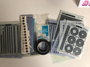
I did this by hand with, I believe, Bishop Graphics pads for the devices and “painted” the r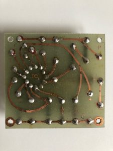 esist on. (Might have used a dry rub-on resist (from Datak?) for the traces. Then I used ferric chloride to remove the copper that wasn’t covered. Interestingly, Bishop Graphics specialized in PCB board drafting supplies, like pads for passive components and IC’s, rolls of different width trace tapes, and more. Then came computer aided design software. The CEO of Bishop Graphics, thought, eh, PCB design using a computer is just a flash in the pan, right? (Dr Wang of Wang Laboratories didn’t see the advent of word processing on IBM PC’s, as well.) That CEO was let go and the new CEO tried to turn the ship around and embrace CAD for creating PCB’s, even selling its own CAD for Mac and IBM PC’s, but it was too late for Bishop Graphics.
My first introduction to using a PCB fab house was using a local company, Kalda Manufacturing, in the Seattle area, (no longer in business apparently) when I was working at Pacific Northwest Bell in the MMC (Minicomputer Maintenance Center).
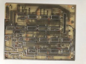 There was a group at the company that monitored and maintained the company’s ESS (Electronic Switching System) central offices; this group had several computers (maintained by my workgroup) that each used a line printer. These printers needed constant maintaining as well as needing to be fed paper all the time. I was asked if I could design a “line printer multiplexor” that would scan the RS232 ports that the line printers were connected to of the PDP11 systems to see if there was a print request. If there was a request, the multiplexor would allow that PDP system to connect to the printer. I designed the circuit using TTL logic and drafted the PCB on a 2X scale on translucent mylar with Bishop Graphics pads and tapes.
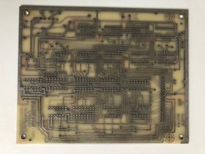 Since I didn’t have a lightbox drafting table for such a purpose, I used a glass coffee table 🙂 with a light shining from below. Not the exactly the most ergonomic way to do the job having to hunch over the table…but I got it done. Dang, I do sorta wish I had kept the 2X completed sheet. Oh well, the lines and pads were starting to come off with age, anyway.